We are not exactly bandits. Bandwidth-Bandits (b2) is a group of IT Pros tackling packets on a daily basis. Each member has their own colorful and unique experience in the evolving field of enterprise data networks, IT security and routing multimedia over IP. The goal of this collaboration is to share knowledge gained from years of experience and pick up new ones from readers. Welcome to our space in the web, please feel free to post what you have in mind.
(b2)
Farewell my fellow IT geeks! As you probably have noticed, I haven't been logging in to post in the forum and I've already deleted my twitter account. I am not leaving IT and/or online scene. I will still be contributing to the online community but will be a different audience. I will be deleting all the contents that I've contributed here. Hopefully, it was helpful to you all. Thank you and farewell!
Just a quick post. I would like to share this helpful PERL script created by Yasin Kaplan,especially to those who use MRTG as part of their daily network traffic monitoring task.
Cisco does not provide an OID for fetching number of VoIP sessions on an IP-to-IP Gateway. One way to plot number of VoIP sessions using MRTG is explained below. You need IOS version >= 12.4 on the Cisco gateway.
IOS command “show call leg active event -log” gives total number of call legs established on a Cisco gateway. Half of this number gives actual VoIP session s established on a Cisco IP-to-IP Gateway:
Cisco#show call leg active event-log
Total call-legs: 268
You can get updated number of sessions information periodically telnet into gateway. MRTG allows console output of shell or PERL scripts as data source in place of SNMP OIDs. Following PERL script can be used to get number of active call legs form a Cisco Gateway:
monitor# more /usr/local/bin/voip_sess.pl
#!/usr/bin/perl
use Net::Rsh;
my $mgw = $ARGV[0];
my $voip_sess;
my @greped;
$a=Net::Rsh->new();
@c=$a->rsh($mgw,"root","root","sh call leg act event-log");
@greped=grep(/^Total/, @c);
You need to add following configuration to Cisco Gateway in order the gateway permit incoming
RCMD request:
ip rcmd rsh-enable
ip rcmd remote-host root 101 root enable
ip rcmd remote-username root
ip rcmd source-interface !
access-list 101 remark **** RCMD Access Control ****
access-list 101 permit ip host 192.168.10.1 any
Finally add a profile to your “mrtg.cfg” script to read number of VoIP sessions. MRTG user must have necessary rights to run “voip_sess.pl” (chmod +x /usr/local/bin/voip_sess).
So you want to have a home voice lab, that is cheap as much as possible?
I hope this short explanation would help you guys out there to decide what are the right equipments to buy.
The first equipment I acquired was 2 units of 2801 for the HQ, you don’t have to worry about the dsp because it has built in dsp and plug and play voice interface card, quite expensive and it cost me a lot
But I have to let go off my 1 unit 2801 so I could buy all the equipment I need to achieve my goal
I bought 2 units of 2611XM, and 1 unit 2621xm, >>> all of these cost me 1/3 price of the 2801.
Gateways
2801 gw (HQ) w/ fxo card
2 units 2611xm gw (Branch) w/ nm-hdv2 –t1 installed w/ pvdm, (borrowed it from a friend), fxo card
2621xm and 2611xm doesn’t have built in dsp’s so you have to buy nm modules for voice
I prefer nm-hdv2 for the gateways (so you could add some pvdm’s cards)
H.323 and MGCP are the only protocol’s that you can simulate for the 2600xm series it does not support sip and sccp protocols. However I can simulate sip & sccp protocol thru my 2801 router
For the endpoints
7960g 2 units w/ poe inj.
7961 1 unit w/ poe inj.
3 host created in vmware with different lan cards and installed with ip communicator (my old pc), “to save some power consumption”
For the call processing
I bought highend pc installed with 64bit Operating system (so I could maximize the memory of the mobo) installed w/ dual lancards, additional lan cards would vary depending on the design you want , for me I used 3 lancards. run them in the vmware, I allocate 1 gig ram of memory every call manager even the Unified presence and cisco unity connection manager.
For the switch (network infrastructure)
2950 1 unit
The strategy is using a different vlan to every sites. in my design I used vlan 2 for the hq and vlan 3 & 4 for the branch
“To get through the hardest journey we need to take only one step at a time, but we must keep on stepping”
(This quick post assumes that the reader knows how to configure Cisco’s proprietary Hot Standby Routing Protocol or HSRP. If you don’t have a basic working knowledge with HSRP yet, please head to Cisco’s website for introductory documentation.)
Scenario:
R. Phoenix was hired by a startup company called Secure4Sure to see if he can circumvent their existing security policies in place in preparation for a 3rd party audit. Before the engagement, both parties were aware of the limitations of the security assessment. R. Phoenix agreed and signed documents, such as a Rule of Engagement (RoE) and a Non-Disclosure Agreement (NDA) document so everything is official and within boundaries.
On the first day, R. Phoenix used his social engineering skills and pretended to be an applicant for a network engineer position posted by the company on a famous job searching website. He handed over his fake ID and resume to the front desk personnel, and was immediately granted a day pass. Off he went to the office of the Senior Network guy for an interview. R. Phoenix immediately noticed the abundance of network cables lying around connected to the wall’s Ethernet port. Old network devices and other gadgets are present as well.
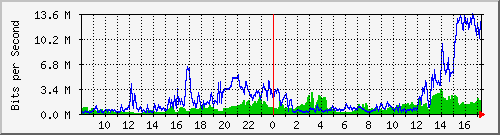
Noticing the lack of a water fountain on the area, R. Phoenix asked the Senior Network guy for a glass of water. The guy politely nodded, asked him to take a seat and went out of the room to get a glass of water. R. Phoenix quickly grabbed a tiny USB device tucked on his left shoe and immediately plugged it in on one of the wall Ethernet ports. He created a small program that automatically sniffs the traffic of an IP network and dumps the result as a text file on his tiny USB drive. It only took him 15 seconds to sniff the IP network; thanks to an unsecured wall Ethernet port.
R. Phoenix went over with the interview and the entire process. Shook hands with the interviewer, surrendered his guest day pass at the front desk, and went straight home. He immediately booted up his computer, launched his favorite packet sniffer program and started to conduct network analysis. He was smiling while scrolling around the packet capture because on his first day, he already has all the information he needed along with a solid plan on how to penetrate Secure4Sure’s network.
He simply saw a multicast traffic to 224.0.02 and he knew what to do next. "The menu for tomorrow is either Denial of Service (DoS) or a possible Man-in-the-Middle (MiTM) attack baby!" he said to himself.
And the rest of the events that unfolded are history.
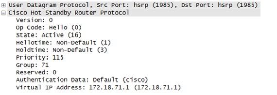
HSRP multicast
No authentication enabled, default password (cisco)
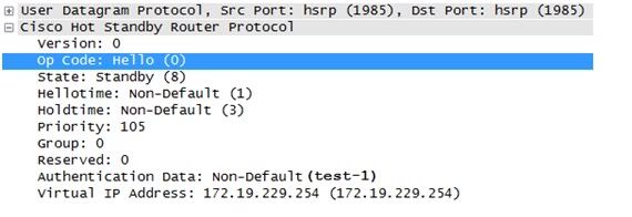
Weak authentication in HSRP, non-default, plain-text password (test-1)
Lessons Learned:
This attack is nothing new. A clever social engineer can easily bypass all your policies and technical controls in place. If someone wants to gain access to your network given enough means, motive, and opportunities (MOM) they will gain access. A bonus to them is lousy configuration on a network device.
What happened with the scenario above is simple; they want high availability on their IP network and they implemented Cisco's HSRP without an acceptable authentication in place. Without an acceptable authentication in place, a rogue router can be inserted in the network to participate in exchange of HSRP traffic (MiTM). This router will be configured with the highest priority so it acts as the primary router in the HSRP network. Then all traffic can be sniffed from this rogue router that the bad guy has complete control.
Because their network traffic was sniffed, an HSRP packet was discovered containing no acceptable authenticaion in place. A bad guy can also forge packets to mess with the HSRP multicast packets; inducing a DoS attack to the network.
Using plain-text passwords for HSRP authentication will suffer the same fate. The solution is to use the command to enable MD5, so the password is hashed and not transmitted as plain text over the network. Hashing provides the elements of confidentiality and integrity.
An Ethernet port without a MAC-based authentication in place is another door of opportunity. The best thing to do is to shut down ports not in use.
One faithful Monday morning and late in the game of planning, your Boss suddenly changed his mind and decided to convert a new retail branch to 100% cloud-based applications. Microsoft Office software will be replaced by Google Apps. The Customer Relationship Management (CRM) Software will be Salesforce.com. And regular phones lines will be replaced by a Softphone-based Voice-over-IP (VoIP) solution, hosted by another Internet Telephony Service Provider (ITSP)somewhere in the Silicon Valley.
As the overall network and systems administrator for your company, you have all the reasons to panic because it will be entirely up to you (or your team if you the benefit and privilege of having people working under you) to make the deployment successful. Due to the unplanned change, the transition will be rough as hell, but its not impossible. Here's a couple of things you can do to overcome this stressful event in your IT life. So, throw away those gadgets and tech books for a while and pull-up a blank spreadsheet file on your PC (or Mac). It's time to put on your Project Manager Hat and take lead.
1. Initiate a emergency meeting with your Boss and the rest of management and discuss the following items according to the order of your preference:
A. The current security controls in effect needs to be adjusted and modifications approved. - Review your Access Control Lists (ACL), IDS-IPS rules, HIPS, HIDS and overall Technical security policies to accommodate the new Port, Protocol and general traffic requirements of the new applications. - Most hosted VoIP applications require opening of an entire range of ports rather than specific ports, think about that. - Some cloud-based applications require either Java or ActiveX running on browsers, think about that as well. - If your company process sensitive information such Credit Card transaction, medical services involving patient information and Personally Identifiable Information (PII) in general, stop and consult your company's legal department because your company might be bounded by PCI-DSS or HIPAA. If this is the case, Cloud Computing might not be suited for your company.
Your security rules will be a mess. But don't worry, you can adjust later. Remember, business goals should drive security policies, not the other way around.
B. Network bandwidth consumption will increase. - Cloud Computing means all the applications are accessed from the Cloud, a.k.a. the Public Internet. You need to start gathering the bandwidth requirements per application that will be running on workstations inside your network. - Prioritize Critical Applications, the best candidate is VoIP because VoIP is very sensitive to bandwidth changes, delay, jitter and packet loss. Unless you want your customer service agents or marketing agents to end up knocking at your door every minute because of robotic sounds, echoing and worst, dropped calls. - Review the Baseline Network Performance of your network (if you have one) and start doing Math. - Use simulators to at least measure how much traffic your network can handle by sending simulated VoIP traffic with the same CODEC (G711, G729, etc.) Choosing the same CODEC is vital in VoIP pre-deployment testing because each CODEC has a different bandwidth requirement. (G711 CODEC consumes 64kbps, G729 consumes 8kbps, etc.) - Hopefully the simulators will help you gauge your bandwidth if you need to add a new T1 line, or a couple. I hope not.
C. Document, Document, Document. - This is where your Project Management skills come in handy. You need to document all major things that have changed, implemented or modified if you want to keep your sanity once each application starts to fall apart. Or worst, your network starts to fall apart after making all those configuration adjustments to accommodate new web-based applications.
Throw away your gadgets and IT books for a while, that spreadsheet I asked you to create will be your personal friend for the initial 2 to 3 months of this project. Treat it as your personal diary where you log all configuration changes, target dates of installation, and all trouble tickets from those cloud-based application vendors.
In a networking job you'll always get into a situation wherein somebody's going to complain about not being able to browse a site or some specific sites. It could be customers of your company or even users within the organization. What do you do when this happens? typically you would browse them by yourself (hopefully your not behind a proxy), then you find out your are able to browse the site. You ask them what troubleshooting steps has been done; where you able to ping the site? have your tried to do an nslookup? changed dns servers? have you tried browsing by IP address? used a public proxy server? tried changing your IP address, etc etc..but most likely, 99% of the time you'll ask them to perform a traceroute to the website. Generally a traceroute will be your most effective troubleshooting tool in these scenarios. It's like the basic swiss knife of troubleshooting routing issues and the likes. Though i know of a bit better one called 'pathping' (Windows only) but most of the time a traceroute will do the work. You'll see every hop, latency on each hop, and the path towards the destination. Probably the best thing you have to keep in mind in using this is that it's only the forward path to the destination. You don't ever see the reverse path unless you do a trace the other way..from the destination to the source. To make that even more challenging is that reverse paths can vary per hop. Imagine that every router always has their own best way around the Internet, and it is normal that every hop/router on the traceroute will have a different path back to the source of the traceroute, and that you don't see unless there something wrong with the trace like a huge spike on the latency where its not expected to.
As a start, traceroutes have different types. They vary on which type of packet they use. These are the most common ones i know: UDP, TCP and ICMP based traceroutes. UDP is the default for Linux, ICMP is the one that's used in Windows and TCP is a another variant which comes by default in Linux but is available for Windows as well as a free download over the net. Now these variants are pretty straight forward. In Linux, the default traceroute uses UDP packets. Most of the time this is fine however there are times that you will encounter target machines that just don't respond to UDP. Honestly there are a lot of them out there!
$traceroute hostname/IP address
Another variant is the ICMP based traceroute. In windows this is the default however it is more known as 'tracert'. By the name ICMP you would immediately know that it uses PING or echo requests as it goes through each hop along the path. So typically if you can ping it then it would respond, with some rare exceptions ofcourse due to firewalls and security policies put in place by organizations.
in Linux:
$traceroute -I hostname/IP address
in Windows:
C:\>tracert hostname/IP address
So basic stuff isn't it? Yes but the trick is knowing how and when to use them. Now probably the best one that I myself prefer. The TCP traceroute almost always does the job when finding out if you can really reach a site. The problem with ICMP and UDP is that not all routers respond to these type of packets. Specially ICMP since most modems nowadays are distributed with ICMP replies disabled as an anti denial of service mechanism. Some do respond but will drop packets every certain interval to prevent against ping floods. Many of them are just turned off since by just turning it on makes you vulnerable to OS fingerprinting. Each OS vendor has their own little tweak on their TCP/IP stack making them identifiable from each other. Redhat has their own, Windows has their own so you know which is which. Therefore attackers would already have a clue on how to attack. Knowing what type of OS and which version is it then what programs are installed, all these would be very important information for hackers around the net. So watch out for that ICMP unless there's nothing really important on your machine and you don't really care. LOL
A lot of times you will see that traceroutes will stop just right before the target machine. Most people will think - Oops there's a problem, i'm not able to reach the site i'm trying to access. Maybe that's why i can't browse that website. Trust me this isn't always the case. Most of the time the target machine just doesn't respond to your requests. Since your trying to access a website. . hmmm. http. .which is TCP port 80, then it would just make sense if you will use TCP packets to probe if the websites http port is accessible.
$tcptraceroute hostname/IP address [80]
Specifying the port is optional. The default is 80 and you may specify other ports e.g. SMTP, FTP, and so on. You'll now then see the target machine respond since you know that it's listening on TCP port 80. Almost every time you'll see a traceroute complete by using this. But there are times that servers/routers are just so secure they just don't respond to anything! even TCP. Maybe due to TCP SYN attacks? who knows. The point is they just stay stealth mode:)
These are the times that you may want to access the server head on. Try telnetting into the server.
$telnet hostname/IP addess 80
Yes trying to get inside the server to make sure you can access it. For secured sites use port 443. Now if it tells you your connected then that's it you proved that you can access the site. But wait. .sometimes there are underlying issues we must not fall for. These are the times that you would like to mimic your browser and send some server requests just to make sure you are indeed able to download the webpages. Why even bother? I was able to access the site via command line. Since your already in the server why not try to see if you are able to download the page.
$telnet www.somesite.com 80 Connected to www.somesite.com. HEAD / HTTP/1.0 press Enter/Return twice!
Texts in bold are the ones you will type.
example:
Passing a HEAD command to the server is sending an http request to download a resource (in this case '/') without actually downloading it. HTTP/1.0 is telling the server its an HTTP 1.0 request. Press Enter to end the request then you may type in some optional request headers then press Enter again to end. In our example we didn't so we just press Enter twice.
note: If you get the code "200 OK" that means it's all good! Also notice that the server told us that its using HTTP 1.1, you may also make your request as HTTP1.1 by using 1.1 instead of 1.0. See how much stuff you can get by this? It even tells you what type of web server it's using and what version. ASP.NET and what version, useful stuff for some:)
To actually download the webpage then you issue the GET command. $telnet www.somesite.com 80 Connected to www.somesite.com. GET / HTTP/1.0 press Enter/Return twice!
This is like actually doing what your browser is doing on the background when you're browsing a website. You will see the source of the page your trying to download by issuing this command. HTML stuff and javascript are common.
sample output:
All you will be able to catch really is just the end of the page because it just blurts it all out on you until it reaches that closing tag of the web page. But you wouldn't really mind because all that matters for us is to know its working!
Now question is why go all the way in doing this? Like what I said there are times that there are issues we do not see or might overlook. Doing these steps would make our troubleshooting much more concrete and will bring us to more accurate conclusions. What if there was an MTU issue along the path? How do you detect that? You send large pings as you can? Even if you do so on the direct gateway of the user its still not guaranteed he/she will be able to browse with the maximum mtu the end device is allowed to. Nothing beats the view from the source device so its always recommended to trust the tests more on their end rather than the tests you do from the middle of the network.
Now if there are routing issues everything i said in this post will be basically useless. Sometimes the source address can be blocked on the target site but that you will detect if traceroutes and telnet fails.
Surprisingly there is always a huge chance the destinaton hop would not be seen in a traceroute, but hey..as long as you are able to reach the last hop router then you can already guarantee there's no problem on your end. Remember that it's the last hop router's responsibility to route to that destination and that it must be a directly connected interface anyway so you're sure its going to route for that unless it's down. If it's not the last hop router then that's where you investigate for blocking or routing issues.
So then watch out for those browsing issues as they're always gonna be around. Understanding how they work and having the knowledge on how to troubleshoot them if they are not accessible through the browser will make things a lot easier for you:)
Please feel free to add or let us know what you think that is wrong to this list by posting your comment below.
Q. How much are the Cisco exams?
CCNA 640-822 costs $125 each attempt. 640-816 costs $125 each attempt. 640-802 (combination for ICND1 and ICND2) costs $250 each attempt.
CCDA/CCNP/CCNP Wireless/CCVP/CCSP/CCDP 64x-??? costs $150 each attempt.
Some people are saying that the new exams for CCNP will be $200 each attempt.
CCNA concentrations (Voice/Security/Wireless)
Exams costs $250 each attempt.
CCDE/CCIE exams
CCIE written exam costs $350 each attempt. CCIE lab exam costs $1,400 each attempt.
CCA (Cisco Certified Architect) exam costs $15K each attempt.
Now, there are some countries that charge tax on top of exam prices.
Q. Do you know where to get cheaper voucher for the Cisco exams? Yes, just go here between 25th - 31st of the month and you will see discounted vouchers. Though, they usually sell the 640-822/816 every single day for $120 but they do sell it cheaper than that during those days that I have mentioned above. There was a time where they were selling the voucher for $75, that's 40% off the original price! Just make sure you're buying the International voucher if you're outside USA/Canada.
Q. Do I need credit card to purchase the voucher?
If you buy it from Vue directly then yes. If you buy it from the site mentioned above then you have the option to pay credit card or PayPal.
In the Philippines, you can call the testing center and ask them to register for you. Once you arrived at the testing center, you can pay the exam fee by cash. Choosing this option will probably cost more than using your credit card.
Q. Is the site above legit?
Of course it is! I won't put it here if it wasn't legit. I have bought three vouchers from them and will continually do so for the next exams that I will be taking.
Q. Are you getting paid to advertise them?
We are not getting paid for this. We are just trying to help you save money!
Q. Where can I take CCNA exam?
Click here and it will tell you the answer. Now, if you're from the Philippines then there are some suggestions that I've read from the thread. MISnet (Makati City) and Database Wizard Inc. (Makati City) are the recommended testing centers.
Q. Can I reschedule my exam?
Yes, you can. If you register the exam from Vue's site then you can do it online. If not, then call the testing center at least 24 hours before your exam date and time or more just to be in the safe side.
Q. What do you recommend self study, CNAP (Cisco Network Academy Program), or bootcamp?
Team members of Bandwidth Bandits will have different opinion about this.
CNAP has its benefits. One of the benefits is access to real equipment and it is an instructor-led training. The materials that are posted from their website are laid out very well. Some, if not all, instructors have been teaching the material for so long so they know the material well enough. Another benefit is access to a special link to avail discounted Cisco Press books up to 45% off. Well, some people do not buy hardcopies anymore because of piracy so that is not a benefit for people that supports piracy. Another benefit is access to Packet Tracer application provided to students and alumni. Again, this may not be viewed as advantage because of piracy. Another benefit I can think of is the discounted voucher if you pass the lab exam. They will give you more than 50% off the exam price if you pass the lab exams. When I was enrolled in CNAP for CCNA, there were only two lab exams. These were easy exams if you've been doing your labs. These vouchers are only for CCNA by the way. Disadvantage of CNAP, it takes three to four semester to finish the CCNA curriculum.
Bootcamp is an instructor-led 5-day or 7-day training. They teach you the materials for short amount of time. You will also have access to real equipment to play with. Some companies will pay for this type of training because they are really expensive. Here in the USA, bootcamps price are ranging from $2K - $5K, depending on which subject. From what I have heard, bootcamps in the Philippines are cheaper than CNAP. Here in the USA, it is the other way around. Community colleges and even high schools are offering CNAP classes and range from $60 - $1K. Normally though, it is less than $300 for one class. When I took my CCNA 1 - 4 from CNAP, I paid about $200 for three semesters in California. When I took my BCMSN class last year here in Illinois, I paid almost $400 for the class. I would've paid almost $1K if I didn't know how to get the discounted rate. Disadvantage of bootcamp is the fast-paced training. Normally, you can't retain all that information crammed to your brain in such a short week.
Self study is the cheapest option out of the three. With what is happening to our world (recession) it is what most, if not all, people are doing. If you take this path, make sure to buy CBT Nuggets or Train Signal materials to help on some of the topics you may have a hard time with.
Q. Which school should I enroll to?
My friend went to Meralco Foundation and he seems to know his stuff. Some suggest University of the Philippines, Mapua, and DLSU. One of the team members of Bandwidth Bandits (Prime) suggests CNCTC.
Q. Which book should I get?
Any Cisco Press books is fine. However, I've been reading comments of other people that Todd Lammle's CCNA book is really good.
Q. What is the passing score in Cisco exams?
Well, you'll see it when you take the exam. It'll let you know how much points you need to accumulate to pass the exam. The maximum points that you can get is 1000. For CCNA, unless they change the passing score, it is 849 out of 1000.
Q. I want to build a home lab, what routers and switches do I need to buy?
Q. I do not have money to spend for a home lab, what should I do?
You can use simulator. Boson is selling simulator. Some books come with simulator for free. You can use Packet Tracer. You can use GNS3 or Dynagen/Dynamips. These two require you to use Cisco IOS. To legally use an IOS, you need to buy the license. However, the EULA may state that you are only supposed to run it on Cisco hardware so it may be a violation.
Q. I heard about CCNP changes, should I take the old curriculum or the new one?
If you can pass the exam(s) by July 31st then by all means take the old curriculum. However, make sure you pass the most important ones first, BSCI and BCMSN. These two exams will be counted towards the new CCNP curriculum. ONT and ISCW won't be counted at all. The new exams consists of ROUTE, SWITCH, and TSHOOT. More info here.
Q. How do I renew my Cisco certification(s)?
It really depends on which certification you're trying to renew. Please click here for more details.
Q. Do Cisco certifications expire?
Yes, every three years.
Q. I let my Cisco certification expired, how can I renew it?
Well, once it is expired then you won't be able to renew it, per se. You need to pass all the exams again starting from CCNA.
Q. I noticed that CCNA Voice is $250 and CVOICE is only $150, should I take CCNA Voice or straight to CVOICE?
I honestly think you should just skip CCNA Voice because of the price. Though, I suggest you to read the book because there are some information there that are important as a VoIP Engineer. Pass the CVOICE and you'll be CCNA Voice.
Q. What are the right combination for the CCNP exam?
BSCI + BCMSN + ONT + ISCW = CCNP <-- All exams should be passed by July 31st BSCI + BCMSN + TSHOOT = CCNP ROUTE + BCMSN + TSHOOT = CCNP BSCI + SWITCH + TSHOOT = CCNP ROUTE + SWITCH + TSHOOT = CCNP
Q. Where can I buy Cisco books?
You can buy them from Powerbooks, National Bookstore, or DataBlitz. You can also try ordering from Cisco Press or Amazon.